Wenzhou Yika Electric Co.,Ltd.
Wenzhou Yika Electric Co.,Ltd. is a professional electric company engaged in the electric power equipment and safety products. such as Fuse Cutout, Fuse Link, Insulators, Busbar Insulator, Lightning Arrester, Disconnector Switch, Circuit Breaker etc. We have specialized team for development, production and marketing, our aim is to develop wide range products with good quality and reasonable price. Our products are exported to more than 15 countries, Including South America, Asian, Middle East and Africa etc. And was Fully affirmed by customers. We believe that we will be able to achieve mutual benefit and win-win situation through our continuous efforts and pursuit.
By YIKA Electric | 17 September 2026 | 0 Comments

Overhead Line Construction: 16 Typical Problems and the Code-Compliant Fixes

The Short Answer

Quality defects in overhead line construction can almost all be attributed to a few recurring issues: non-compliant grounding systems (regarding trench excavation, welding, and down-lead height), inadequate protection at cable terminations and entry/exit points, incorrect spacing of line hardware, improper assembly of transformer platforms, and substandard erection of poles or towers. These issues can lead to consequences such as non-compliant grounding resistance, phase-to-phase short circuits, small animal intrusion into enclosures, and the tilting of poles or towers. The solution lies not in increasing inspection frequency, but in strictly enforcing standards at the source: ensuring grounding trench depths of 600 to 800 mm, maintaining a minimum spacing of 700 mm between insulation-piercing connectors and fuse stationary contacts, using heat-shrink tubing on cable cores, securing identification tags with bolts, and ensuring pole burial depths of 1.7 to 2.3 meters.
Introduction: How Construction Quality Issues Lead to Operational Failures
The seeds of premature failure in overhead power lines are often sown on the very day the poles are erected. Issues such as trenches being 100 mm too shallow, welds lacking anti-corrosion treatment, or stripping 200 mm more insulation than necessary from the conductor core—none of these are visible in photos taken on the day of installation. Yet, they inevitably manifest later as non-compliant grounding resistance, short circuits, and unplanned power outages.
This article outlines 16 typical issues observed during the construction of overhead distribution lines, categorized into six key operational areas. For each issue, we detail the nature of the defect, its consequences, and the relevant regulatory requirements. These standards are based on practical construction experience and reference Chinese national standards—specifically GB 50173 (*Code for Construction and Acceptance of 66kV and Below Overhead Power Lines*) and GB 50169 (*Code for Construction and Acceptance of Grounding Devices for Electrical Installations*)—while also aligning with internationally recognized practices such as IEEE Std 81 (grounding measurements) and IEC 60364-5-54 (earthing arrangements and protective conductors). Whether you are a contractor, a power engineering technician, or a project owner, this checklist will help you prevent rework and operational failures before they occur.
1. How do grounding defects lead to failures?
(Questions 1–3)
Grounding systems represent the area where construction defects are most concentrated among "hidden works"—installations that are neither visible nor accessible after backfilling and are only revealed during acceptance testing or upon the occurrence of a failure.

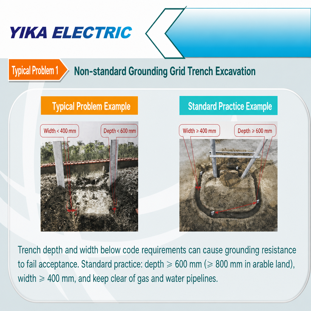
Problem 1: Non-standard excavation of grounding grid trenches
     
Defect:
Insufficient trench width and depth—commonly less than 400 mm in width and less than 600 mm in depth.
Consequence: The grounding electrode fails to make adequate contact with the soil, resulting in a failure to meet acceptance standards for grounding resistance.
Standard requirements: Trench depth must be at least 600 mm (at least 800 mm for arable land) and width at least 400 mm; trenches should not be located close to gas or water pipelines.
Problem 2: Irregular grounding body welding

Defects:
Insufficient welding length and welding surface, no anti-rust treatment; insufficient length of anti-corrosion treatment at the welding area.
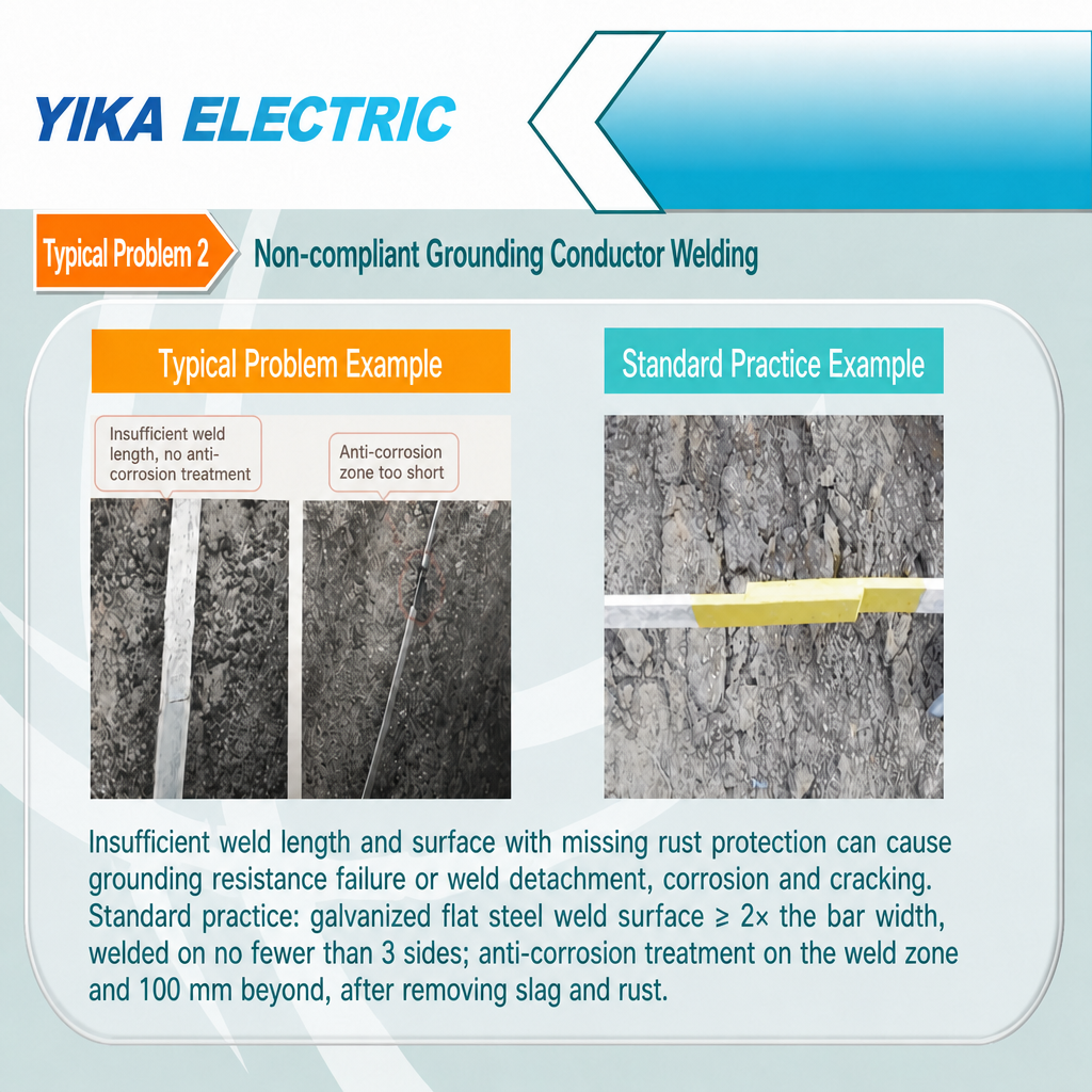
Consequences: The ground resistance is unqualified, and the joints desolder, rust, and crack over time—the ground path quietly disappears.
Specification requirements: The welding surface of galvanized flat steel shall not be less than 2 times its width, and the welding shall be carried out on no less than three sides; the welding part of the grounding device and the outside 100 mm shall be treated with anti-corrosion treatment. The surface welding slag and rust must be removed before anti-corrosion treatment.


Problem 3: Irregular installation of grounding device

Defect:
The height of the PVC casing set on the upper body of the ground lead is less than 3 m.
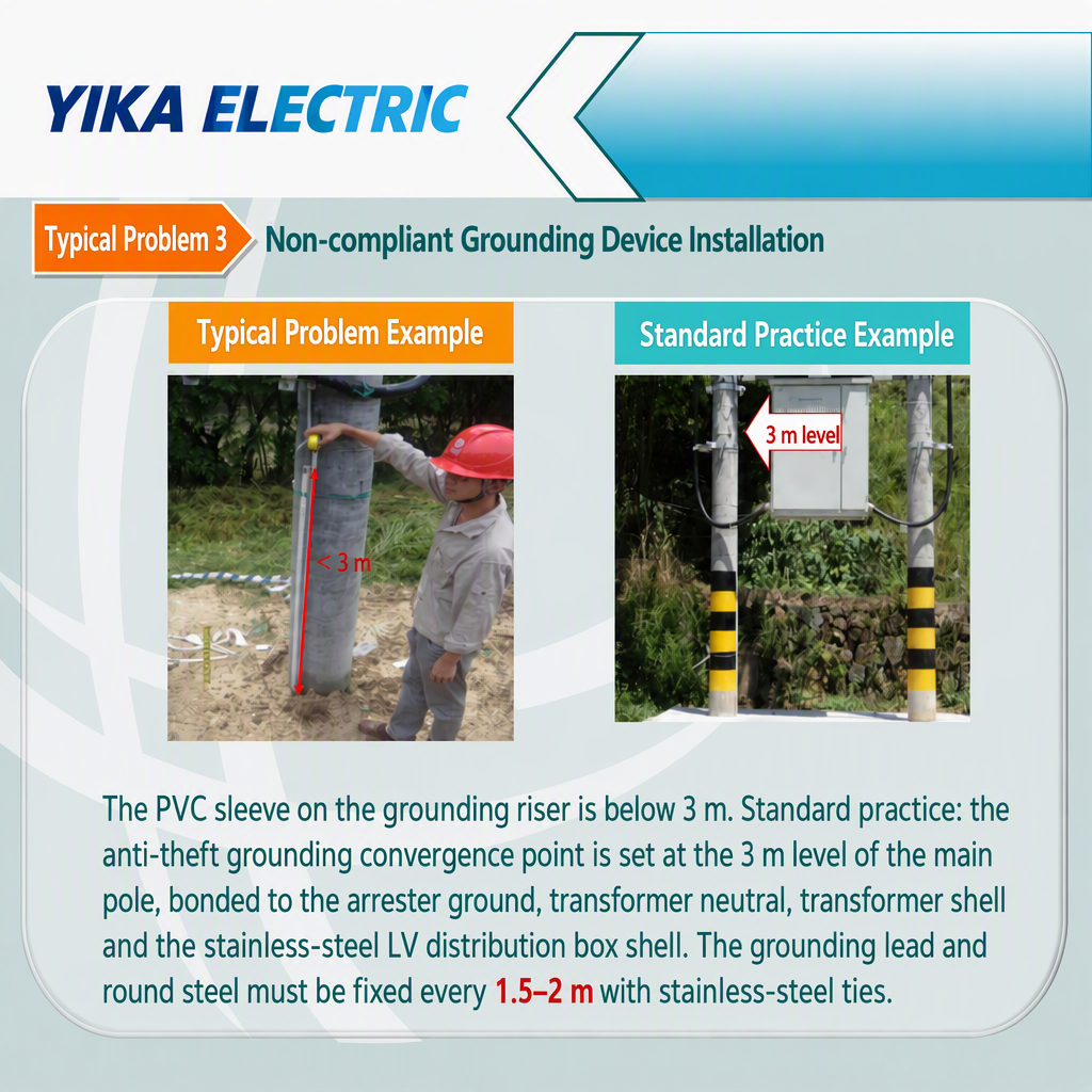
Consequences: The upper section of the lead is exposed and is prone to being stolen and mechanically damaged; lack of protection at the junction will weaken the entire grounding system.
Specification requirements: The anti-theft ground electrode meeting point is set at 3 m from the main pole, and is effectively grounded with the arrester ground, transformer neutral point ground, transformer shell ground, and stainless steel low-voltage integrated distribution box shell; the ground lead and ground round steel are fixed at a fixed point every 1.5–2 m, and are tied and fixed with stainless steel ties.


2. Why is hardware spacing important?
(Questions 4 and 10)
Hardware positioning and spacing are classic examples of "small details with major consequences"—they impact maintenance safety and mechanical integrity, not merely appearance.

Problem 4: Insufficient clearance between the insulation-piercing grounding clamp and the fuse's stationary contact.

Defect:
The clearance between the insulation-piercing grounding clamp and the upper terminal of the fuse does not meet requirements.
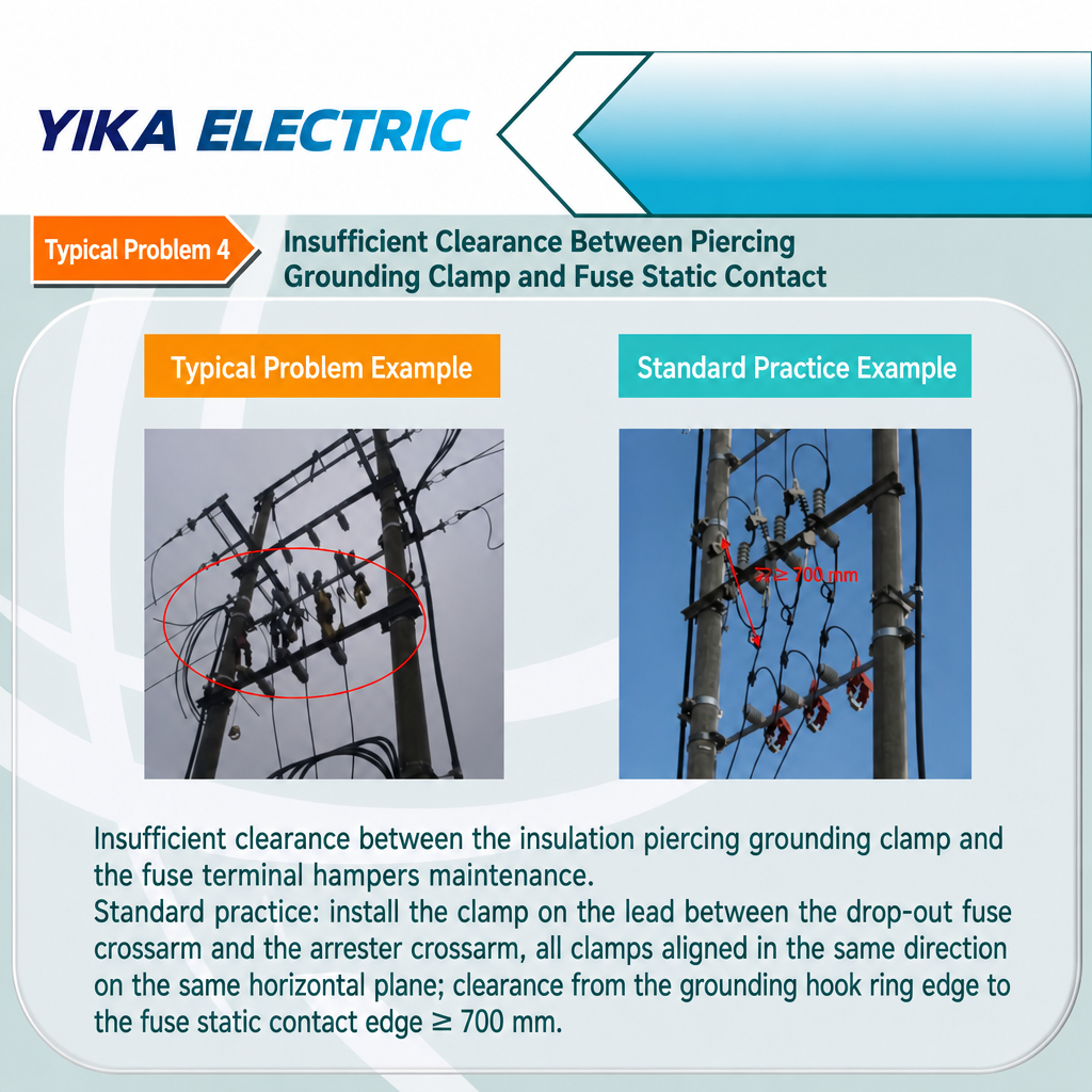
Consequences: Equipment inspection and maintenance become difficult and unsafe, particularly when replacing fuses or performing live-line work.
Standard Requirements: The clamp must be installed on the lead wire between the crossarms of the dropout fuse and the lightning arrester, with consistent orientation and alignment on the same horizontal plane; the distance between the edge of the grounding attachment ring and the edge of the dropout fuse's stationary contact must be at least 700 mm.


Problem 10: Incorrect installation position of the post insulator for the upper lead of the dropout fuse.

Defect:
The post insulator for the upper lead of the dropout fuse is not secured to the crossarm.
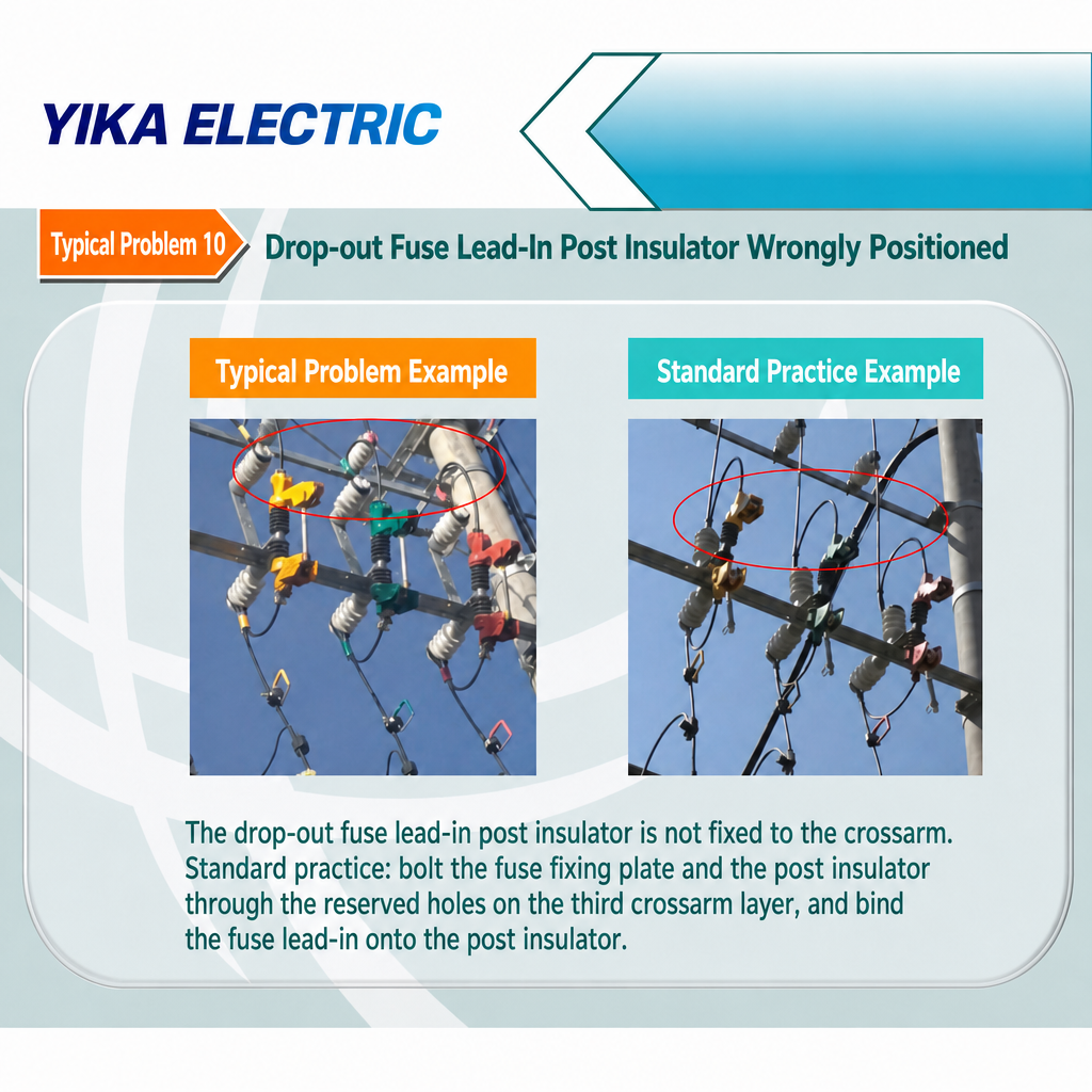
Consequences: Conductor tension and vibration cause the lead to loosen, resulting in poor contact and arcing, which ultimately leads to a phase conductor fault.
Standard Requirement: The fuse mounting bracket and post insulator must be bolted to the designated mounting holes on the third-level crossarm, and the upper lead must be securely tied to the post insulator.
3. How can the enclosure and cable entry/exit points be protected? (Questions 5, 6, 13, and 14)
Every cable entry or exit point acts as an invitation—inviting in water, small animals, and mechanical damage. Four of the 16 typical issues center on this area.

Problem 5: Lack of proper drip loops on incoming and outgoing cables of the JP cabinet.

Defect:
No drip loops were formed on the incoming/outgoing cables at a point lower than the cable entry/exit ports.
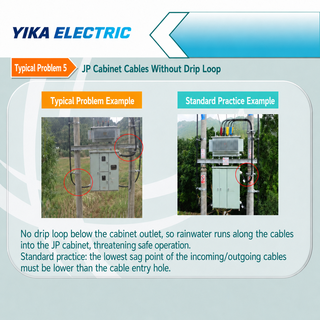
Consequence: Rainwater flows along the cables into the JP cabinet, compromising insulation and safe operation.
Standard Requirement: The lowest point of the sag in incoming/outgoing cables or insulated wires must be lower than the entry/exit ports—a proper drip loop ensures rainwater drips off before entering the cabinet enclosure.


Problem 6: Improper treatment of cable entry/exit openings in the JP cabinet.

Defect:
Cable entry/exit openings in the JP cabinet are not sealed.
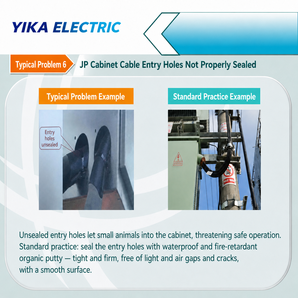
Consequence: Small animals (snakes, rodents, birds) may enter the cabinet, causing short circuits and equipment failure.
Standard Requirement: Seal openings tightly and securely using waterproof and fire-resistant organic sealing material; ensure there are no gaps allowing light or air leakage, no detachment, and that the surface is smooth and even.


Problem 13: Galvanized steel pipe not properly used for cable pole-mounting; galvanized steel pipe not grounded.

Defect:
No galvanized steel pipe used to protect the cable where it ascends the pole; or, if a steel pipe was used, it was not grounded.
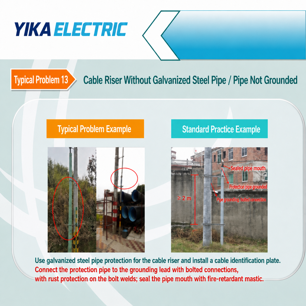
Consequences: The cable is susceptible to damage at the base of the pole; an ungrounded protective steel pipe can become energized during a cable fault, posing an electric shock hazard.
Standard Requirements: Galvanized steel pipe must be used to protect the cable where it ascends the pole (extending to a height of at least 2 m), and a cable identification tag must be installed; the connection between the protective pipe and the grounding lead must be bolted (with anti-rust treatment applied to the grounding bolt weld); pipe ends must be sealed with fire-resistant sealant; and the protective pipe must be grounded at both ends.


Problem 14: Incorrect cable entry/exit method

Defects:
Unsatisfactory workmanship; vertical spacing of cable supports fails to meet requirements; incorrect cable entry/exit configuration.
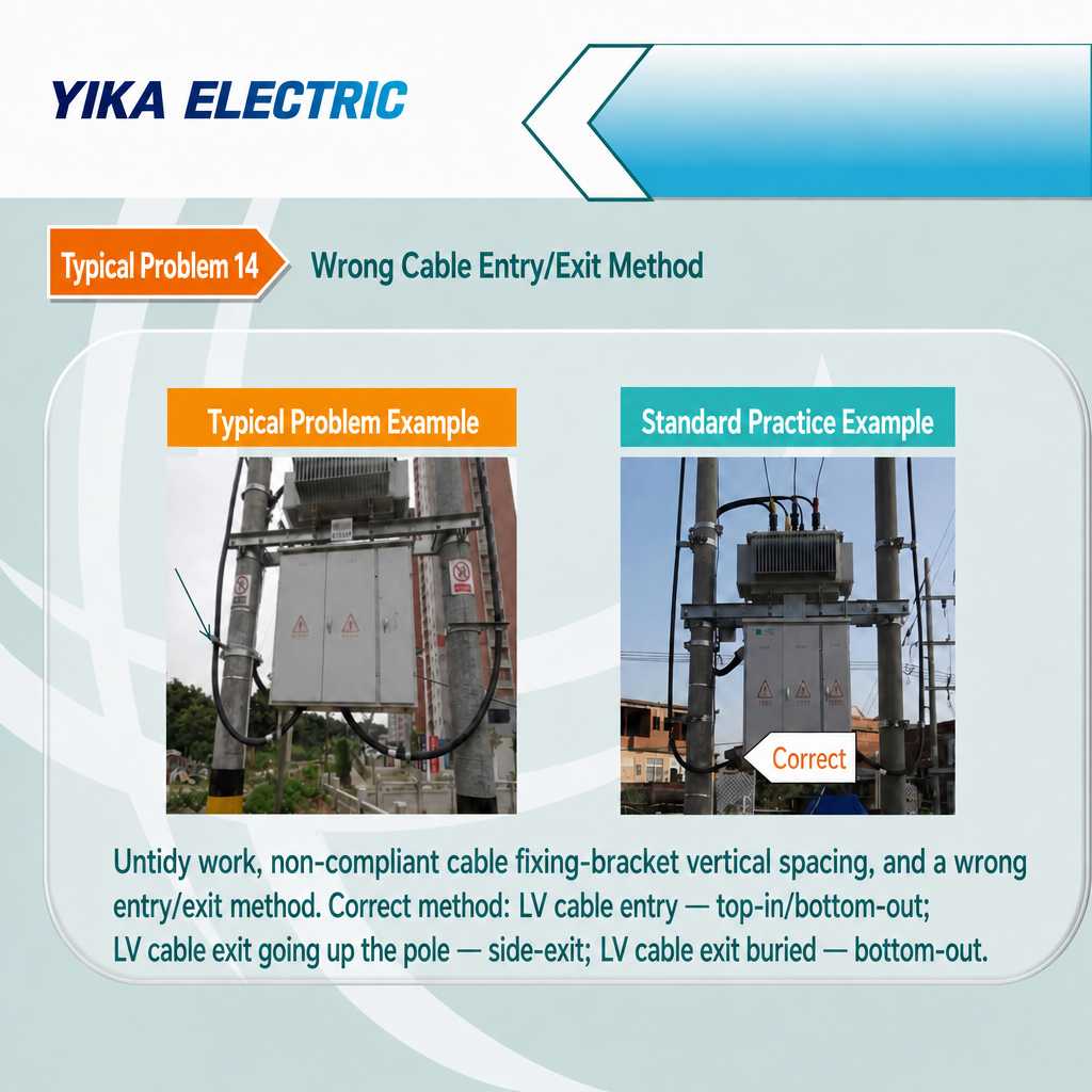
Consequences: Uneven stress on cables; messy appearance; accelerated insulation wear at bends.
Standard Requirements: Use standard routing—low-voltage cable entry should be top-in/bottom-out; low-voltage cable exit to poles should use a side-exit configuration; underground low-voltage cable exit should use a bottom-exit configuration.


4. What should be done regarding cable terminations? (Questions 7, 8, and 15)
The quality of the termination directly determines whether insulation integrity can be maintained under load and aging conditions. Three of the 16 issues relate to termination defects—precisely because this is the step most frequently rushed during field installation.

Problem 7: Disorganized conductor cores and exposed conductors lacking insulating heat-shrink tubing during low-voltage cable termination.

Defect:
Excessive stripping of the insulation layer; exposed conductor cores lack heat-shrink tubing protection.
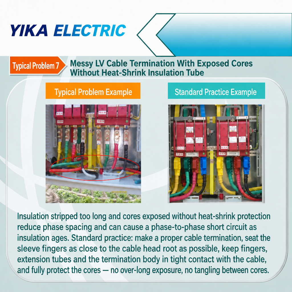
Consequences: Insufficient phase-to-phase safety clearance; risk of phase-to-phase short circuits due to insulation aging.
Standard Requirements: When preparing cable terminations after stripping the insulation, the breakout boot (finger sleeve) must be positioned as close as possible to the base of the cable end. The breakout boot, extension tubing, and termination components must fit tightly against the cable to ensure the conductor cores are fully protected, thereby preventing excessive core exposure and the intertwining of cores.


Problem 8: Poor workmanship in the installation of transformer low-voltage incoming cables; absence of insulating protective covers on terminal posts.

Defect:
Transformer high- and low-voltage incoming and outgoing lines lack insulating protective covers; installation workmanship for low-voltage incoming lines is substandard.
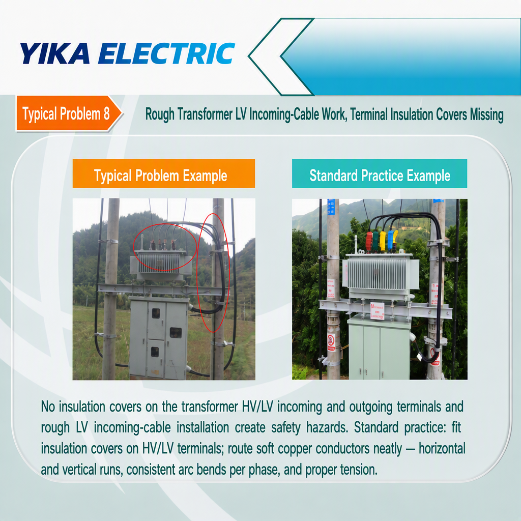
Consequence: Poses a direct safety hazard—accidental contact with live terminal posts during inspections or maintenance.
Standard Requirements: Transformer high- and low-voltage incoming and outgoing lines must be fitted with insulating protective covers; flexible copper conductors must be arranged neatly (horizontally and vertically), with uniform bending radii across phases and appropriate tension.


Problem 15: Exposed cable cores on low-voltage outgoing cables

Defect:
The cores of the low-voltage outgoing cables are exposed at the pole-top termination point; standard heat-shrinkable insulating sleeves were not installed as required.
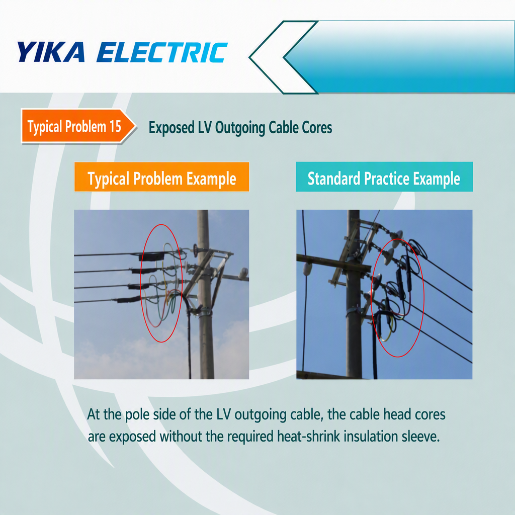
Consequence: Same as Issue 7—reduced phase-to-phase clearance, creating a risk of short-circuiting at the most vulnerable point of the line.
Standard Requirement: Standard heat-shrinkable insulating sleeves must be installed on all outgoing cable cores at the pole-top termination point before the termination is completed.


5. What are the requirements for transformer mounting platforms? (Questions 9 and 16)
Pole-mounted transformer platforms support the heaviest equipment and bear the greatest mechanical loads on the line; assembly errors here constitute both electrical and structural issues.

Problem 9: Transformer identification plate not installed according to standards

Defect:
The transformer's operational ID plate is not secured with bolts.
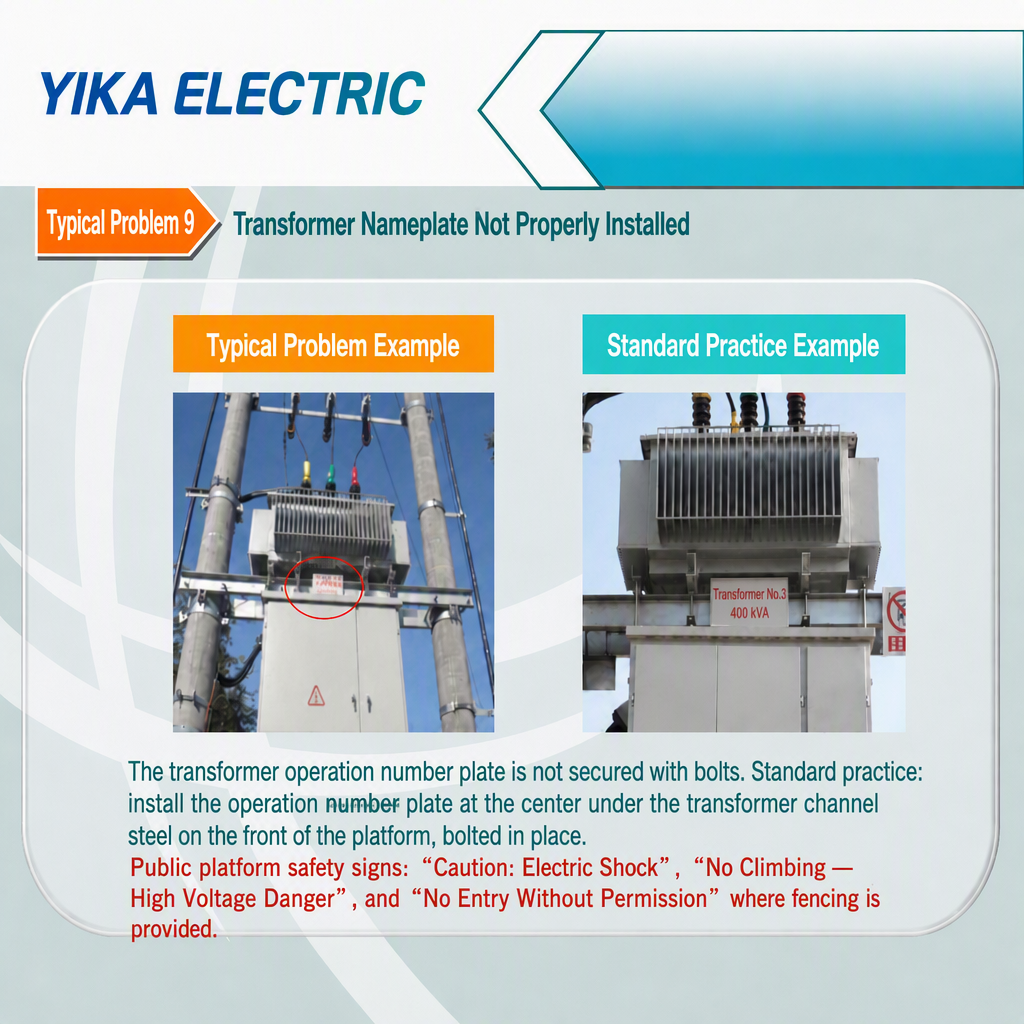
Consequences: The plate may detach or shift, preventing operating personnel from identifying the equipment—a practical issue during switching operations and fault handling.
Standard Requirements: The operational ID plate must be installed in the center position beneath the transformer's channel-steel mounting base on the front of the distribution transformer structure and secured with bolts. Safety signage for public distribution transformer sites must include "Caution: Risk of Electric Shock" and "Danger: High Voltage – No Climbing"; if a perimeter fence is installed, "No Entry Without Authorization" signage is also required.


Problem 16: Failure to install double cross-arms for the high-voltage section of the transformer platform as required.

Defect:
A single cross-arm was used for the high-voltage section of the transformer platform.
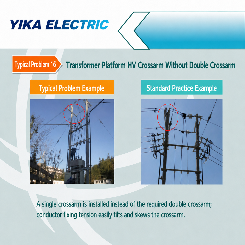
Consequences: The load from the secured conductors can easily cause the cross-arm to tilt or become misaligned, disrupting conductor geometry and placing excessive strain on theinsulators.
Requirement: Install double cross-arms in accordance with standard design specifications to balance conductor loads.


6. How can tower/pole tilting and hazards on the roadside be prevented? (Questions 11 & 12)
Remedying structural issues after the fact incurs the highest costs—re-erecting a pole costs several times more than properly constructing the foundation in the first place.

Problem 11: Leaning of Erected Poles or Towers

Causes of Defect:
Failure to apply pre-set inclination to the foundations of tension or angle towers with narrow bases; backfill for concrete poles not compacted; incorrect use of base plates and anchor plates; terminal or angle poles not properly aligned.
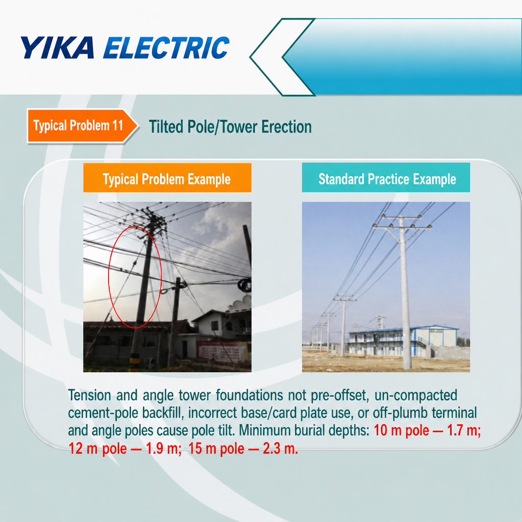
Consequences: Progressive leaning of the pole under load, reduction of safety clearances, and eventual structural failure.
Standard Requirements: Backfill must be compacted; base plates and anchor plates must be used correctly. Minimum burial depths: not less than 1.7 m for 10 m concrete poles; 1.9 m for 12 m concrete poles; and 2.3 m for 15 m concrete poles.


Problem 12: Lack of anti-collision markings on poles located near the road.

Defect:
Utility poles situated near the road lack the required anti-collision markings.
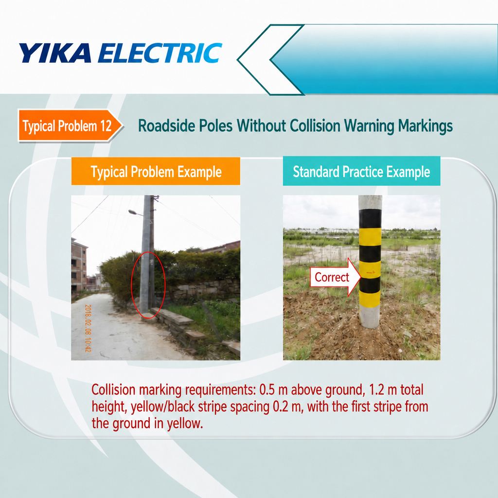
Consequences: Vehicle collisions could damage the poles and power lines; the poles become virtually invisible in low-light conditions.
Standard Requirements: Anti-collision markings must start 0.5 m above ground level and have a total height of 1.2 m; the spacing between yellow and black bands must be 0.2 m, with the bottom-most band (starting from the ground) being yellow.


Quick Reference Checklist: 16 Common Issues

NO.

Typical Issue

Main Consequence

Standard Requirement

1

Substandard grounding grid trench excavation

Substandard grounding resistance

Depth ≥600 mm (≥800 mm for cultivated land), width ≥400 mm

2

Improper grounding electrode welding

Joint detachment, rust/cracking

Weld surface ≥2× flat steel width; weld on ≥3 sides; apply anti-corrosion coating 100 mm beyond weld

3

Improper grounding device installation

Vulnerable to theft/cutting; weak grounding

Junction point at 3 m; secure with stainless steel ties every 1.5–2 m

4

Insufficient clearance between piercing connector and fuse stationary contact

Unsafe maintenance

Clearance ≥700 mm; uniform orientation; same plane

5

No drip loop on JP cabinet incoming/outgoing cables

Rainwater ingress into cabinet

Lowest point of cable sag must be below the entry/exit hole

6

Unsealed cable entry/exit holes in the JP cabinet

Small animal intrusion, faults

Seal tightly with waterproof and fire-resistant sealing compound

7

Low-voltage cable cores exposed and disorganized

Phase-to-phase short circuit

Install heat-shrink tubing and breakout boots to protect cable cores

8

Transformer incoming line installation is substandard; no protective cover

Electric shock hazard

Install insulating protective covers on high- and low-voltage incoming/outgoing lines; ensure wiring is neat and aligned (horizontal and vertical)

9

Transformer identification plate not installed according to specifications

Unable to correctly identify the equipment

Bolt-mounted at the center of the mounting platform front; equipped with safety signage

10

Incorrect positioning of fuse lead-wire insulator

Loosening, arcing

Bolt to the third cross-arm; secure lead wire with binding

11

Tower/pole tilting after assembly

Structural failure

Burial depth: 10 m → 1.7 m; 12 m → 1.9 m; 15 m → 2.3 m

12

Roadside pole lacks anti-collision markings

Damage from vehicle impact

0.5 m above ground; 1.2 m total height; yellow base section; 0.2 m spacing

13

Galvanized steel pipe not used for pole-mounted cable / Steel pipe not grounded

Cable damage, risk of electric shock

Galvanized steel pipe length ≥ 2 m; bolted grounding connection; pipe ends sealed; grounding at both ends

14

Incorrect cable entry/exit method

Cable subjected to mechanical stress; reduced insulation lifespan

Top entry/bottom exit; pole-top side exit; underground/buried exit

15

Exposed conductor cores on low-voltage outgoing cables

Risk of short circuit

Install heat-shrinkable tubing on each conductor core

16

Single cross-arm used instead of double cross-arms for the transformer station's high-voltage connection

Cross-arm tilted due to load

Install double cross-arms in accordance with standard design specifications

Frequently Asked Questions (FAQ)
Q: What are the most common reasons for non-compliant grounding resistance during overhead line construction?
A: Improper trench excavation and welding. Trenches shallower than 600 mm (or narrower than 400 mm) fail to establish sufficient soil contact; undersized or non-corrosion-protected welds deteriorate over time—corresponding to issues 1 and 2 mentioned above.
 
Q: How deep should grounding trenches be excavated?
A: According to distribution network construction practices, the minimum depth is 600 mm and the width is 400 mm; for cultivated land, the depth must be increased to 800 mm. Trenches should be kept away from gas and water pipelines.
 
Q: Why must heat-shrinkable insulating sleeves be installed on cable cores?
A: Insufficient clearance between exposed cores (after stripping) creates a risk of phase-to-phase flashover or short circuits as insulation ages. This requirement applies to both cable termination assembly (Issue 7) and pole-top cable heads (Issue 15).
 
Q: What is the required spacing between the insulation-piercing grounding clamp and the drop-out fuse?
A: The distance from the edge of the grounding attachment ring to the edge of the fuse's stationary contact must be at least 700 mm; additionally, the clamps must face the same direction and lie in the same horizontal plane.
 
Q: Why must insulating protective covers be installed on transformer terminals?
A: High- and low-voltage terminals are live. Without protective covers, a single accidental touch during routine inspections or maintenance could result in electric shock; installing covers combined with proper wiring is a standard requirement.
 
Q: What burial depth is required for concrete poles to prevent tilting?
A: At least 1.7 m for 10-meter poles, 1.9 m for 12-meter poles, and 2.3 m for 15-meter poles. Backfill must be compacted, base plates/anchor blocks used correctly, and foundations for tension and angle poles must incorporate pre-set offsets.
 
Q: How should cable entry and exit openings on JP cabinets (integrated distribution cabinets) be sealed?
A: Use organic sealing materials that are both waterproof and fire-resistant. The seal must be tight and secure, free of cracks, light leaks, or air gaps, and have a smooth, even surface finish. Failure to seal openings allows small animals to enter the cabinet, potentially causing short circuits.
 
Q: What safety signs should be installed at public distribution transformer sites?
A: "Caution: Risk of Electric Shock" and "Danger: High Voltage – No Climbing"; if a fence is installed, it must include "No Entry Without Authorization."

Get the job done right the first time.
None of these 16 defects are obscure or complex issues. They are routine, day-to-day errors that determine whether a line operates reliably for twenty years or fails after just twenty months—and almost every one of them can be identified by qualified contractors and competent field engineers during the construction phase. Print out the checklist above and use it for on-site verification; this transforms acceptance testing from a game of chance into a straightforward, systematic procedure.
 
If you are selecting equipment for overhead distribution projects—such as insulators, line hardware, fuses, surge arresters, or disconnect switches—YIKA ELECTRIC offers components designed for longevity and compliant installation to support contractors and utility companies. Please send your project Bill of Materials (BOM) to sales@yika-electric.com / nicki@yikaelectric.com  and we will help you address every detail critical to line reliability.


Leave a Reply

Your email address will not be published.Required fields are marked. *
Name
E-mail
Content
Verification code
ver_code